
While checking the operation of motor number 3 on the platform, the electrician engaged the breaker and immediately heard crackling inside the motor control center (MCC) breaker cabinet, according to a report from the Bureau of Safety and Environmental Enforcement (BSEE). The MCC cabinets are metal enclosures that house components such as variable frequency drives, motor starters, resistors, contactors, circuit breakers, fuses, disconnect switches, and overload relays. They play a very important role in the industrial power control and distribution systems.
As the electrician opened the MCC breaker cabinet, he smelled smoke and saw a 1⁄2” flame under the control transformer. He immediately used a fire extinguisher to extinguish the flame and instinctively removed the breaker cabinet’s fuses and resistors to prevent any other possible flare-up and to eliminate all possible connectivity within the MCC breaker cabinet. He then performed a Lockout/Tagout by placing a lock on the breaker arm to ensure no power could circulate.
In reviewing the near miss incident, investigators found:

- Three bolts/nuts on the bus bar connecting the breaker to the bus straps were either loose or damaged prior to energizing the circuit. A bus bar is a metallic strip or bar (typically copper, brass or aluminum) that conducts electricity within a switchboard, distribution board, substation, battery bank, or other electrical apparatus. Its main purpose is to conduct a substantial current of electricity, and not to function as a structural member. This resulted in the bus bar heating up the circuit and causing an overload of current on the transformer. Additionally, the bolts/nuts had not been inspected recently to determine if they had been properly torqued or damaged prior to operation.
- Insulation on the bus bar behind the breaker showed signs of significant dust build- up as evidenced by visible electrical surface track marks. This dust likely caused an electric arc. Electrical surface tracking is a phenomenon where an electric current burns the top layer of an insulation material and allows the current to migrate across the insulation and ultimately cause damage. Electrical surface tracking is defined as the number of seconds that a material resists the formation of a surface conducting path when subjected to an intermittent arc of high voltage and low current characteristics.
- Insulation suffered damage on two wire connections that travel from the breaker/bus bar to the control voltage transformer.
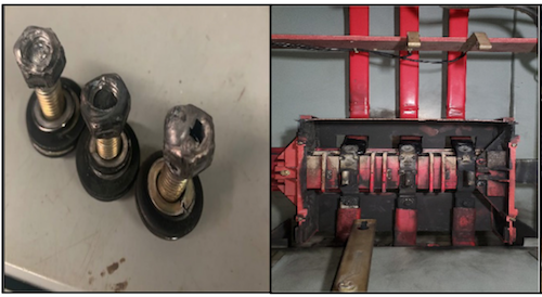
Damaged bus bar bolts, left, and damaged bus were at the center of an electrical fire on an offshore production platform.
Source: BSEE
In light of the investigation, BSEE recommends operators and contractors consider the following:
- Establish inspection and maintenance policies/procedures to include:
— Scheduling the examination of electrical systems
— Conducting an infrared or thermographic inspection in accordance with manufacturer’s recommendations, and document this inspection
— Measuring insulation resistance and testing polarization index before an MCC is re-energized (after installation or regular maintenance)
— Examining all barriers/insulators and replace any that show signs of arcing damage, tracking, excessive heat, or cracking
— Inspecting all power and control wiring, replacing any wire that has worn insulation or shows signs of overheating or cracking - Develop a quality control policy/procedure that provides guidance for inspection/maintenance that specifically addresses potential electrical issues, including dust accumulation on the bus bar
- Ensure bolts/nuts are properly torqued to the Original Equipment Manufacturer specifications and inspect them for damage prior to energizing the circuit
- Document all repair and/or replacement of electrical components. When changes are made to the electrical distribution system, update and distribute all applicable drawings and maintenance schedules to reflect the changes
- Examine all bus bars and connectors, and replace any parts that are badly discolored, corroded, pitted, etc. Establish a replacement schedule for parts subjected to excessive temperatures